


This f-250 has morning issues

Diagnostic Digest Volume 1
Kyle was hoping for a quiet Friday afternoon at the Kempt garage. He was still recovering from a bad sunburn and the aftereffects of overeating incurred during the recent Memorial Day weekend. Any hope of a quick and peaceful end to the workweek ended when a local farmer, Ben Gleaner, drove up in a 2011 Ford Super Duty truck with a 6.7L Turbo Diesel.
“Kyle, this thing is harder to get going in the morning than my old hound,” exclaimed Ben. A cursory glance at the Ford told Kyle that there was more than one dog at the Gleaner farm. “Don’t wash that thing Ben, the dirt is the only thing holding it together,” Kyle said with a grin.
Ben told Kyle how the truck needed a long crank time to start on a warm day but that it would start eventually. However, if it was below 50˚F, he could crank it past the point where he thought he would overheat the starter but still with no signs of the mighty 6.7L starting.
Kyle tried to direct Ben to the local Ford dealer with instructions to trade it in but Ben would have none of that. Besides, the recent pandemic was still limiting vehicle supply and the price of a new truck was a bit steep for a farmer who saw retirement on the near horizon.
And if the IPC thought it was receiving invalid temperature data from the Powertrain Control Module (PCM), it would set the temperature gauge to cold and set the U0401:00.
Kyle convinced Ben to leave the truck for the weekend. Kyle parked it outside the shop in hopes that it wouldn’t be there come Monday morning.
Unfortunately, the Ford still graced the corner of the lot Monday at 6:30 AM when Kyle rolled up. Although it might reach 80˚F later that day, it was currently
below 50°F. Kyle figured the first order of diagnosis was to try to bring the truck to life. After 30 seconds of cranking the engine was unwilling to make some happy Diesel racket.
Where to start on this no-start? Grabbing a scan tool Kyle checked the fuel rail pressure during cranking. Knowing that it takes 5000-psi to open the injectors, he was satisfied with the 6,800-psi measured by the Fuel Rail Pressure (FRP) sensor. The Fuel Rail Temperature (FRT) sensor showed a value consistent with the brisk morning temperature, but he didn’t bother to the check coolant temperature PID. There were no Powertrain codes noted, but there was a network code, U0401:00, in the Instrument Panel Cluster (IPC). Kyle was about to look that code up, but customers were trickling in and the F250 had to wait.
It was 3PM and the temperature outside was just over 80˚F before Kyle could jump on the Ford truck again. Remembering what Ben told him about being able to start the engine in the afternoon, Kyle turned the key to “start” and after cranking eight seconds the Diesel came to life. Being a good diagnostician, he used all his senses and noted that there was a lot of fan noise for a cold engine. Perhaps the fan clutch was always engaged? “Not that important now,” he thought.
Kyle let the beast idle for a few minutes while he finished buttoning up a timing chain on a Chevy Malibu 4-cylinder.
He came back to the truck that was still chattering away. Grabbing the scan tool again he looked at the live data and everything looked normal … except the coolant temperature. The ECT Parameter Identification (PID) value read 298°F. “What the hey,” Kyle shouted. There were no signs that the engine was actually overheating and an IR thermometer aimed at the coolant hoses showed temperatures in the high 190s. And weirdly, the dashboard temp gauge was stuck firmly on “COLD.”
What about that network code? What about that noisy fan? Kyle knew it was time to pull up service information and see what common factors existed.
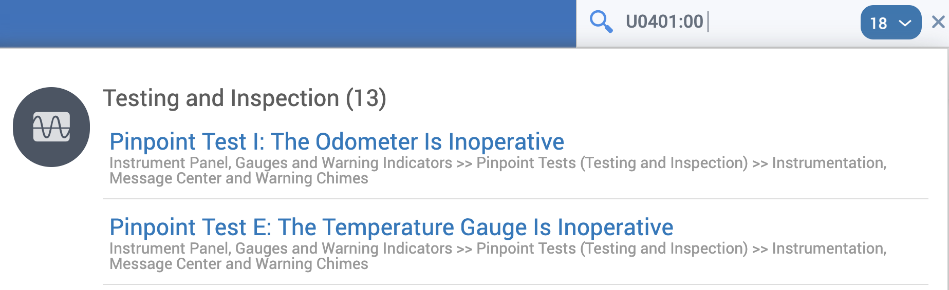
The code definition and code setting criteria shed some light on the situation:
“If the engine coolant temperature (ECT) data is deemed invalid by the IPC, the IPC sets DTC U0401:00 and defaults the temperature gauge to cold (C).”
What about the noisy fan?
“The PCM optimizes fan speed based on engine coolant temperature, the engine oil temperature, the fuel rail temperature, the transmission fluid temperature, the intake air temperature, or air conditioning requirements.”
Kyle considered that if the PCM thought the engine was too hot it would command the cooling fan clutch (viscous drive) to go to 100% duty cycle and the fan would spin at a speed worthy of a Boeing 747 engine at take-off.
And if the IPC thought it was receiving invalid temperature data from the Powertrain Control Module (PCM), it would set the temperature gauge to cold and set the U0401:00.
But what about the no-start on cold mornings? If the PCM thought the engine was warm, what else would be affected? A little research revealed that the Glow Plugs might not be energized during a cold start.
Here’s what Kyle found regarding the Glow Plug Control Module (GPCM):
The glow plug system is electronically controlled by the GPCM. If the coolant temperature is below 60°C (140°F), the GPCM energizes the glow plugs immediately after the key is placed in the ON position. Then, depending on the readings from the Engine Coolant Temperature (ECT) sensor, as well as the battery voltage, the GPCM determines how long the glow plugs are energized.
Given the ultra-high ECT PID and the temperature gauge stuck on “COLD,” Kyle knew he had to focus on how the PCM gets coolant temperature information.
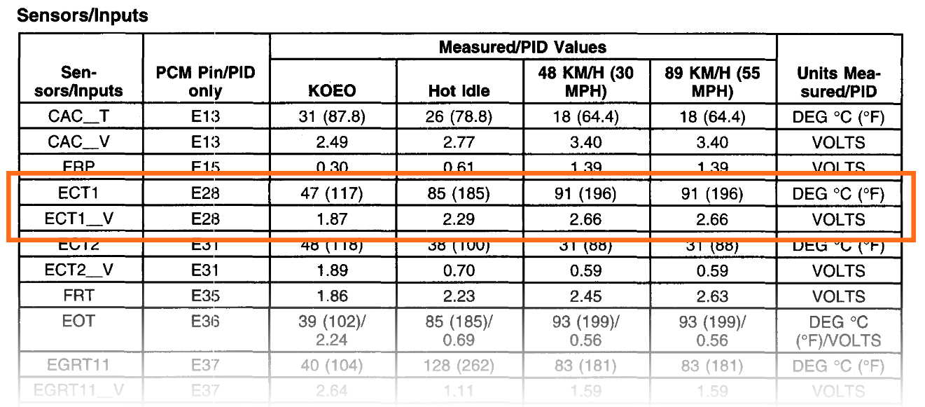
He found that there are two ECT sensors on this engine: ECT 1 and ECT 2. One feeds coolant temperature to the PCM and the IPC; the other is associated with EGR cooler monitoring. Both are Negative Temperature Coefficient (NTC) sensors whose resistance decreases as they get hotter. Having a two-pin connector, both sensors are wired with a reference voltage on one pin and a ground on the other pin. As the sensors get hotter they pull the reference voltage lower and lower.
A typical ECT PID temperature value should indicate -40º F when disconnected. If the ECT reference voltage is jumped to the ECT signal wire (which is grounded through the ECM), the ECT PID should typically indicate approximately +300º F.
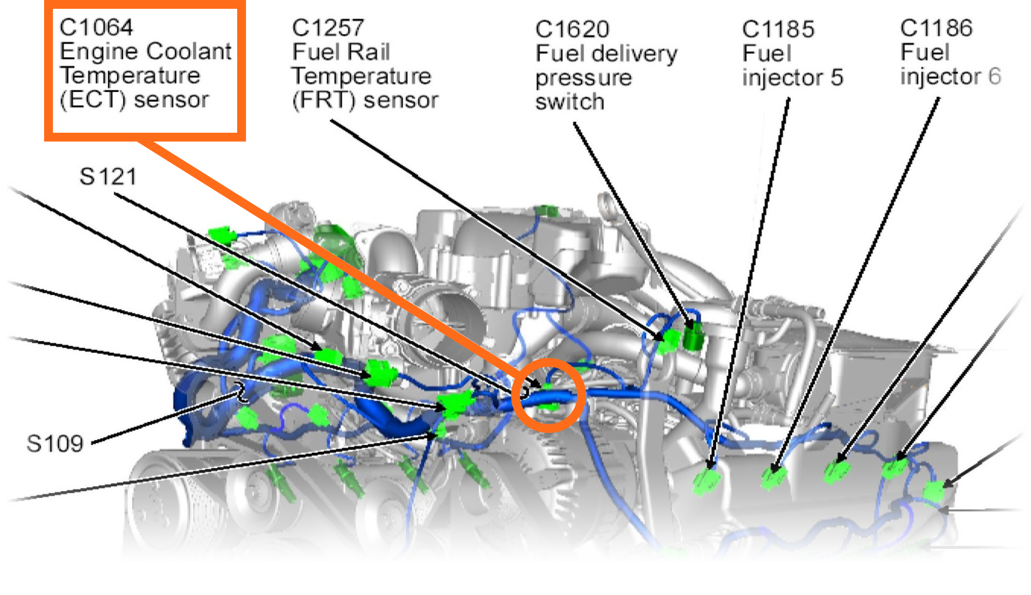
Kyle chose to focus on ECT 1. While monitoring the ECT PID he unplugged the ECTG sensor connector. The PID value should have gone to -40º F. Instead it stayed at 298°F.
Examining the wiring diagram showed that a yellow wire, circuit VE716 traveled from the PCM to the ECT connector C1064 PIN 1. Kyle determined that PIN1 should have a PID voltage value of approximately 5 volts with the connector unplugged. Plugged in and the engine at normal operating temperatures the PID value should be around 2.6 volts. Kyle grabbed his trusty Fluke meter and found that the measured voltage value at PIN 1 was the same zero volts as shown on the scan tool.
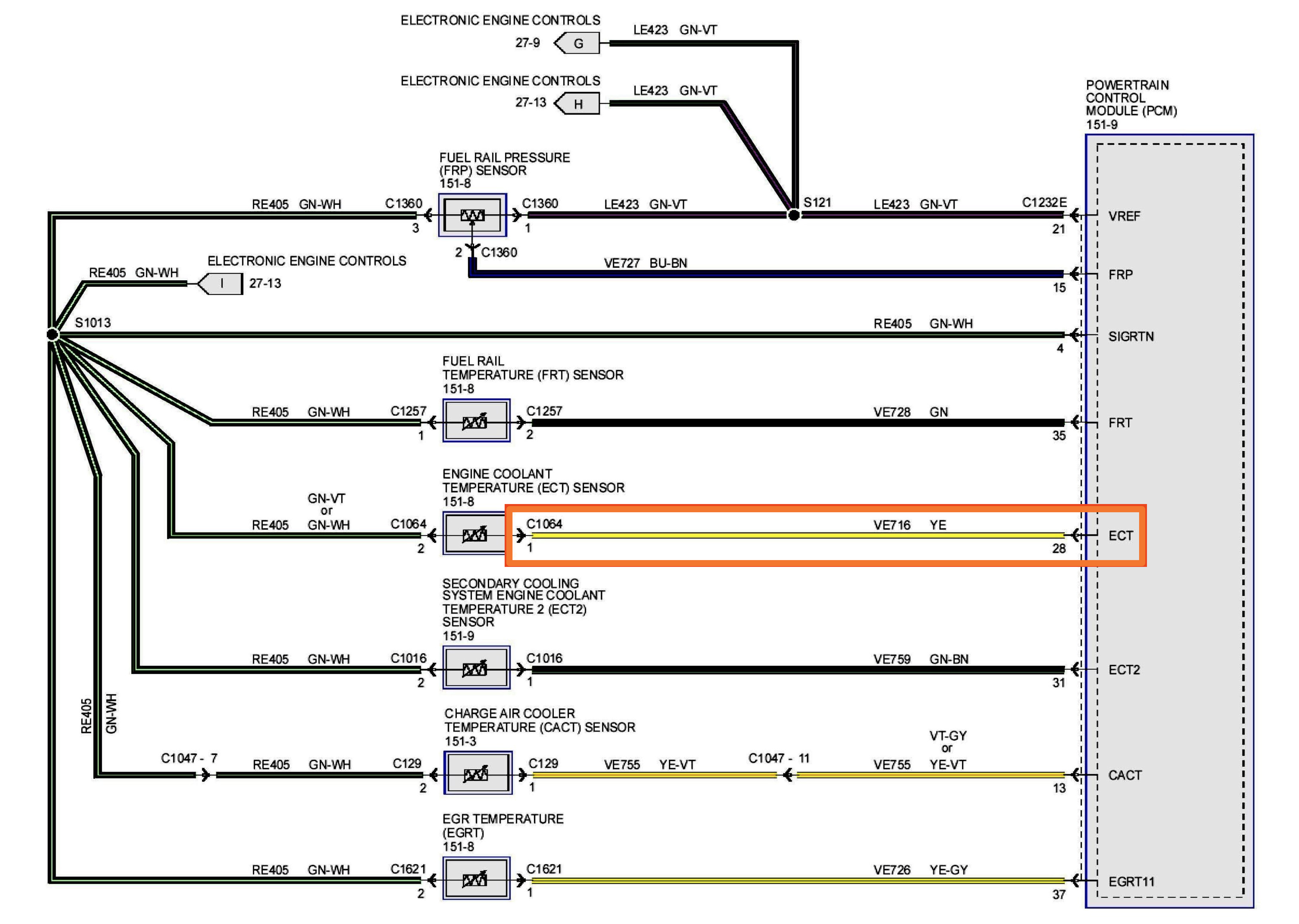
This led him to two likely conclusions: a short to ground on the yellow VE716 wire or a bad PCM. A distant third possibility was that the PCM connector C1232E had some pins bent together or corrosion shorting the pins. Kyle went for the easy-to-check route and focused on the yellow VE716 wire. As it turned out, this wasn’t so easy to check. The harness routing was complex and twelve years of farm life had not been kind to the engine compartment. Unwrapping the harness would take several hours of labor just to confirm or deny that the yellow wire was shorted.
Kyle called Ben and the farmer asked him to avoid spending more than two hours of additional labor.
Kyle contemplated the situation: how could he accurately determine the problem, then fix the truck quickly, and still make a good quality repair?
To confirm the cause of the problem Kyle first disconnected the batteries and unplugged the PCM connector C1232E. He located the yellow wire at PIN 28 of C1232E. And then he snipped that wire two inches from C1232E.
He then plugged the C1232E back in, reconnected the batteries, and now the scan tool showed -40º F on the ECT PID temperature value and 5V as a voltage value. The problem was found: somewhere within four feet of harness the yellow VE716 wire was shorted to ground. Perhaps on a bracket or a clamp; at this point it did not matter.
What Kyle did was snip the ECT connector end of the yellow VE716 wire two inches from C1064 and graft a new wire between C1064 and C1232E. Then he used high-quality, self-sealing connectors and taped everything up. Now it’s the prettiest thing on the truck and he verified that all is back to normal.
Tuesday morning was another cool one, but even cooler was the 6.7L Turbo Diesel that fired up in less than two seconds of cranking. If only Ben could get his dog to follow the Ford’s quick-start example, life on the farm would be just about perfect.
Editors Note: Diagnostic Digest uses real life diagnostic scenarios with appropriately ficticious characters and locations to illustrate real world diagnostic techniques.
Want to see how ALLDATA can improve shop efficiency? Check out our suite of products, each designed to contribute to both shop efficiency and productivity.
If you would like to read more articles like this one please subscribe to ALLDATA News.
