


What’s Load Got To Do With It?
The trouble code you extracted from that car seems to point you to a bad sensor. You replace the sensor and the code quickly comes back. Hmm, must be a bad module!
So that gets replaced as well. No one is more surprised than you when the original code comes back. Well, that leaves the wiring and connectors. You disconnect the harness at the sensor and the module end and check for wiring and connector continuity. Your meter shows zero Ohms resistance. You determine it cannot possibly be the wiring or connectors. Or could it be?
Only the Good Die Young
To the naked eye, and to the Ohm meter, a bad wire may look much like a good wire. If the wire left the factory with 20 strands of the finest copper but due to 5 years of flexing only 5 strands are intact, a DVOM will show that wire to have acceptable resistance. That wire may only be able to handle 100 milliamps, but the meter is happy because it is only loading that wire with 2 to 10 milliamps.
 Before Testing
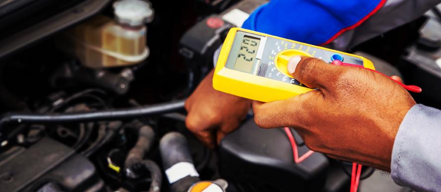
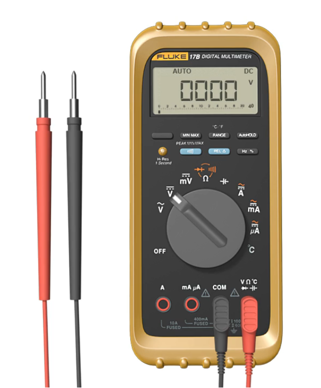
Use a quality digital Volt/Ohm meter (DVOM). Validate your DVOM using a known-good source of voltage. The display should show approximately 12.6 Volts when the leads are touching the posts of a known-good battery. The display should read zero when nothing is connected to the test leads. Many meters have a “low-battery” indicator. Replace the battery if needed. I know this seems obvious, but don’t use a meter for voltage testing that cannot accurately measure voltage. As obvious as it may seem to check your test equipment before testing circuits, we have observed technicians perform multiple tests with bad meters, test leads, or incorrect meter settings.
Work it out
We need to make that wire and its connectors work hard to expose their weaknesses. No strain, no gain. There are a few ways to accomplish this. Let’s examine them.
Voltage Drop
If the component attached to the circuit normally draws over 200 milliamps/0.2 Amps (actuators, motors, injectors, etcetera), voltage drop testing is a great way to determine if the positive and negative sides of the circuit are functioning as designed. In a perfect world the connectors and wires would pass all the voltage to the components and take none for themselves. The fact is, anything that has current passing through it will take
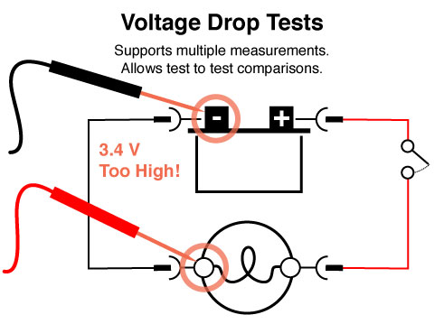
Figure 1
some voltage for itself because everything has resistance. This includes fuses, switches, battery terminals, and grounds. Resistance produces a drop in voltage available within a circuit. The good news is that a quality DVOM can measure that loss of voltage. We call that loss “voltage drop.” In most circuits, voltage drop that exceeds 100 millivolts/0.10 Volts is cause for concern. Note: starter motor wiring may drop about a volt and be normal; this is an exception to the 100 millivolt guideline.
Voltage that “drops” on its way to the component is voltage that cannot be used to operate that component. A positive voltage supply circuit for fuel injector that drops 2 Volts will result in the fuel injector receiving 10.6 Volts from a 12.6V circuit. While cranking, the 12.6 Volts is closer to 10.5 Volts. This means that those injectors are now operating with 8.5 Volts. Throw in a weak battery, dragging starter motor, or thick oil, and the injectors may not open.
“The fact is, anything that has current passing through it will take some voltage for itself because everything has resistance. This includes fuses, switches, battery terminals, and grounds.”
Here’s how to measure voltage drop: place the meter probes at the start and finish of either the positive OR negative side of a circuit. You will be checking both sides – but ONLY one at a time. If the meter is NOT auto-ranging set the meter on 20 Volts DC (the symbol is two parallel lines). Any voltage that cannot flow through the circuit will be displayed on the DVOM. That displayed voltage is “voltage drop.” (Figure 1)
All voltage drop produces some heat. Excessive voltage drop produces excessive heat. On high current circuits such as starter motors or Diesel glow plugs, the voltage drop can discolor wiring and connectors. Be on the lookout for this type of damage in high current circuits.
Remember total voltage drop is the sum of all the individual drops in a circuit. 50 millivolts of drop across each connector in a five-connector circuit is 250 millivolts. Make sure you check the entire circuit, both power and ground sides. (Figure 2)
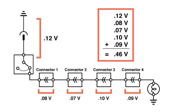
Figure 2
Loaded Testing of Wiring
This method works well when testing wiring associated with sensors, although it can be used to check any type of wiring that carries up to 15 Amps. We use the wiring to carry current and gauge its ability to carry current by the brightness of a common automotive light bulb.
Here are a variety of simple testing tools you can purchase or create to test a circuit’s ability to carry current and to verify that the wiring in a circuit is performing as it should. These tools will give you a little variety of different loads and ways to connect them.
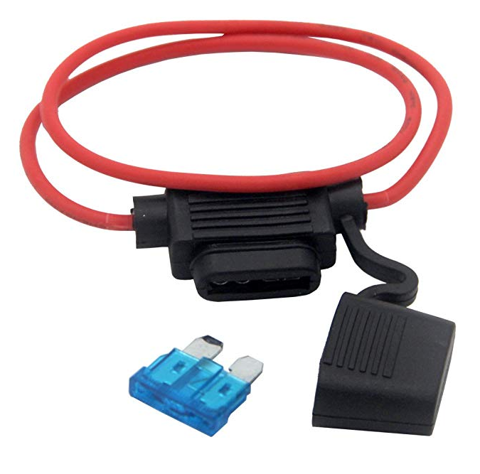 |
A length of 16-gauge wire outfitted with an inline fuse holder equipped with up to a 15 AMP fuse (with a variety pack of bladed fuses to fit your inline fuse holder) |
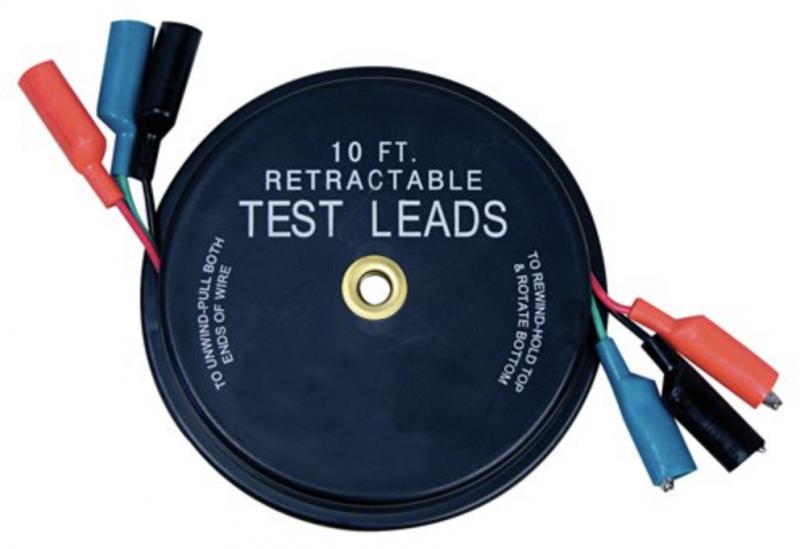 |
Jumper leads |
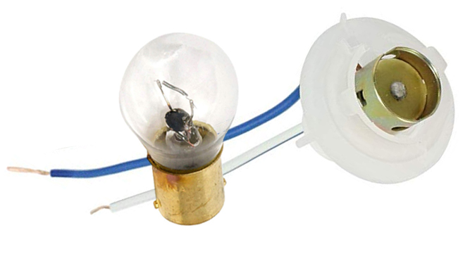 |
Light bulb (1156) and two-wire connector |
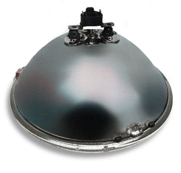 |
Sealed-beam headlamp |
How to Perform the Test:
Choose a lamp that would stress but not overload the circuit. The 1156 is fine for sensor circuits; the headlamp is perfect for wiring and connectors used in actuators and motors (and similar circuits) drawing up to 15 AMPS.
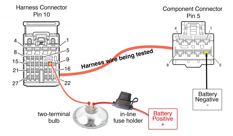
Figure 3
- Isolate or disconnect the wiring you want to test so the wires are no longer connected to the harness or the component(s).
- To perform the test, connect the inline-fused side of your test lamp (bulb) lead to the battery positive (+) terminal or good known power source. Connect the other test lamp lead to one end of the vehicle’s wiring harness connector you want to test (PIN 10, Image 1).
- Connect a jumper wire from the other end of the harness wire (PIN 5, Image 1) you’re testing to the negative (-) battery terminal or good known ground.
- If the lamp shines as bright as it did when connected directly to battery, the wire is good. If it doesn’t illuminate or is dim, the vehicle’s wire is defective.
- To add another dimension and accuracy to the test; especially if you have a hard time judging lamp brightness, you can measure the voltage drop across the lamp to see if the voltage is the same as when it was connected directly to the battery. (Figure 3)
Armed with these tests you’ll be less likely to replace a good component with another good component when the problem is really wiring and connectors. And you’ll be fixing cars faster and more accurately. That is the goal we should all be striving for.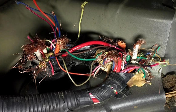
Lastly, don’t forget to perform a thorough visual inspection of the wiring before grabbing any testing tool. If you’re lucky, you’ll find an obvious problem created by critters that have a taste for wiring.
Critter chewed wires!
Want to see how ALLDATA can improve shop efficiency? Check out our suite of products, each designed to contribute to both shop efficiency and productivity.
If you would like to read more articles like this one please subscribe to ALLDATA News.
