Chevrolet Volt, Ford F-150 Repair Procedures
In Part 1 of this Tech Tip, we discussed how accurate and timely OE collision repair information can help production managers:
- Improve vehicle throughput to ensure on-time vehicle delivery.
- Accelerate technician efficiencies and production.
- Reduce outsourcing of repairs.
- Simplify repairs on complex, technically challenging vehicles.
The manufacturer is the authority. Who else knows which components are made from which types of steels, exotic alloys, plastics or other materials; where to section without compromising the crush zone; the causes and repairs for issues that arise after a model leaves the factory? And what better source is there for ensuring that the vehicle drives from your shop in a safe condition?
For this article, specific examples of OE procedures, diagrams, specifications, technical service bulletins (TSBs) and safety precautions are taken from ALLDATA Collision S3500.
Part 1 featured:
- 2011 Lexus parking assist system — calibration process
- 2011 GM vehicles — TSB covering a power steering leak
- 2012 Infiniti M56 — identifying new materials
Part 2 (this article) features:
- 2011 Chevrolet Volt — front suspension frame, removal and replacement
- 2010 Ford F-150 – steering gear, removal and replacement
Here are some excerpts from current OE repair articles and TSBs found in ALLDATA Collision S3500.
Service Information
Always refer to ALLDATA for safety procedures, identification of material types, recommended refinish materials, and removal and installation procedures. Always refer to the vehicle manufacturer for questions on applicable or non-applicable warranty repair information.
Structural Component R&R: 2011 Chevrolet Volt
- Drivetrain and front suspension frame replacement
(This is an example only. For space considerations, references to associated procedures and subassemblies have been deleted.- Disable the high voltage system. Refer to High Voltage Disabling.
- Disconnect the negative battery cable from the battery.
CAUTION: With the wheels of the vehicle facing straight ahead, secure the steering wheel utilizing the steering column anti-rotation pin, steering column lock or a strap to avoid damaging the SIR system or causing it to malfunction. The steering wheel must be secured in position before disconnecting the following components:- Steering column
- Intermediate shaft(s)
- Steering gear
- Support the radiator and condenser from above using the condenser tabs on each side.
- Remove the front bumper fascia.
- Install the engine support fixture.
- Remove the lower steering intermediate shaft bolt.
DANGER: Do not use a service jack to lift this vehicle. Lifting the vehicle with a jack could cause the vehicle to slip off the jack and roll, which could cause injury or death. - Raise the vehicle on a hoist.
- Remove the front tire and wheel assemblies.
- Remove the catalytic converter.
- Remove the front wheelhouse liner.
- Remove the wheel speed sensor wiring harness (2) from the frame on both sides (Figure 1). Remove the wiring harness retainers (3) from the frame and the lower control arm (Figure 1).

- Remove the heater inlet and outlet pipe bolts from the frame.
- Position the heater water auxiliary pump and support to the side.
CAUTION: Electrostatic discharge (ESD) can damage many solid-state electrical components. ESD-susceptible components may or may not be labeled with the ESD symbol. Handle all electrical components carefully. Follow these precautions to avoid ESD damage:- Touch a metal ground point to remove your body’s static charge before servicing any electronic component – especially after sliding across the seat.
- Do not touch exposed terminals. Terminals may connect to circuits susceptible to ESD damage.
- Do not allow tools to contact exposed terminals when servicing connectors.
- Do not remove components from their protective packaging until required to do so.
- Avoid the following actions unless required by the diagnostic procedure:
- Jumping or grounding of the components or connectors.
- Connecting test equipment probes to components or connectors. Connect the ground lead first when using test probes.
- Ground the protective packaging of any component before opening. Do not rest solid-state components on metal workbenches or on top of TVs, radios or other electrical devices.
- Disconnect the electrical connectors from the electronic power steering assembly.
- Remove the wire harness bracket and bolt from the power steering gear.
- Remove the lower ball joints from the steering knuckles.
- Remove the stabilizer link nut from the strut, then discard the nut.
- Remove the outer tie rods and tie rod nuts from the steering knuckles.
- Remove the rear transmission mount through-bolt.
- Lower the vehicle until the drivetrain and front suspension frame contact the engine support table.
- Remove the frame front bolts (1) (Figure 2).
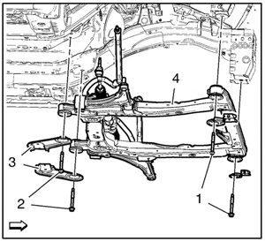
- Remove the frame rear bolts (2) (Figure 2).
- Remove the frame reinforcements (3) (Figure 2).
- Remove the frame (4) from the vehicle (Figure 2).
- Remove the following components if replacing the frame:
- Lower control arms
- Stabilizer shaft
- Radiator support brackets
- Steering gear
- Rear transmission mount
Installation Procedure
Refer to Fastener Caution.
- Install the following components on the drivetrain and front suspension frame, if removed:
- Rear transmission mount
- Radiator support brackets – Tighten the fasteners to 22 Nm (16 lb. ft.).
- Stabilizer shaft
- Lower control arms
- Steering gear
- Install the frame to the vehicle.
- Install the frame rear bolts (2) and tighten to 160 Nm (118 lb. ft.).
- Install the frame front bolts (1) and tighten to 160 Nm (118 lb. ft.).
- Install the frame reinforcements (3) and tighten to 58 Nm (43 lb. ft.).
- Install the rear transmission mount through-bolt.
- Install the outer tie rods and tie rod nuts to the steering knuckles.
CAUTION: ESD can damage many solid-state electrical components. ESD-susceptible components may not be labeled with the ESD symbol. Handle all electrical components carefully. Use the following precautions in order to avoid ESD damage:- Touch a metal ground point in order to remove your body’s static charge before servicing any electronic component – especially after sliding across the vehicle seat.
- Do not touch exposed terminals. Terminals may connect to circuits susceptible to ESD damage.
- Don’t allow tools to contact exposed terminals when servicing connectors.
- Do not remove components from their protective packaging until required to do so.
- Avoid the following actions unless required by the diagnostic procedure:
- Jumpering or grounding of the components or connectors.
- Connecting test equipment probes to components or connectors. Connect the ground lead first when using test probes.
- Ground the protective packaging of any component before opening. Do not rest solid-state components on metal workbenches or on top of TVs, radios or other electrical devices.
- Install the wire harness bracket to the power steering gear. Tighten the wire harness bracket bolts to 9 Nm (80 lb. in.).
- Connect the electrical connectors to the electronic power steering assembly.
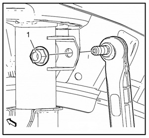
- Install the NEW steering linkage tie rod. Tighten the steering linkage tie rod nut to 65 Nm (48 lb. ft.) (Figure 3).
- Install the lower ball joints to the steering knuckles. Refer to Lower Control Arm Replacement.
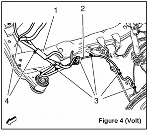
- Install the wheel speed sensor wiring harness (2) to the frame on both sides. Install the wiring harness retainers (3) to the frame and the lower control arm (Figure 4).
- Install the heater water auxiliary pump and support to the frame.
- Install the heater inlet and outlet pipe fasteners to the frame.
- Install the front tire and wheel assemblies.
- Install the catalytic converter.
- Install the front wheelhouse liners.
- Lower the vehicle.
- Remove the support of the radiator and condenser.
- Install the lower steering intermediate shaft.
- Remove the engine support fixture from the vehicle.
- Install the front bumper fascia.
- Check the wheel alignment.
- Enable the high voltage system.
- Connect the negative battery cable from the battery.
Structural Component R&R: 2010 Ford Truck F-150 4WD
Service and repair, removal and replacement:
- Steering gear
- Special tool
Required Material
NOTICE: While repairing the power steering system, care should be taken to prevent the entry of foreign material or failure of the power steering components may result.
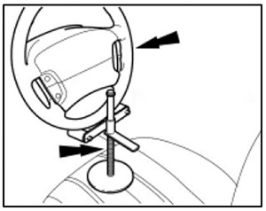
- NOTE: Use a steering wheel holding device. Using a suitable holding device, hold the steering wheel in the straight-ahead position (Figure 1).
- Remove the front wheels and tires. For additional information, refer to Wheels and Tires.
- If equipped, remove the skid plate bolts and the skid plate.
- NOTICE: Do not allow the steering column to rotate while the steering column shaft is disconnected or you may damage the clockspring. If there is evidence that the steering column has rotated, the clockspring must be removed and re-centered. For more information, refer to Restraint Systems.
- Remove the steering column shaft-to-steering gear bolt and disconnect the steering column shaft.
- NOTE: New O-ring seals must be installed any time the lines are disconnected from the steering gear.
- Remove the power steering line clamp plate bolt and disconnect the pressure and return lines.
- Discard the O-ring seals.
- Remove and discard the two outer tie-rod end nuts.
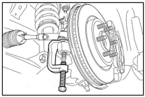
- NOTICE: Use care when installing the Ball Joint Tool Separator or damage to the tie-rod end boot may occur.
- Using the Ball Joint Tool Separator, separate the outer tie-rod ends from the wheel knuckles (Figure 2).
- Using the Ball Joint Tool Separator, separate the outer tie-rod ends from the wheel knuckles (Figure 2).
- Remove the two steering gear bolts and nuts.
- Remove the steering gear through the LH wheel opening.
Installation
- Install new O-ring seals on the pressure and return lines.
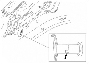
- NOTICE: Make sure the LH steering gear bushing is seated correctly or failure of the steering gear may occur. The RH side bushing does not have locking tabs (Figure 3).
- Install the steering gear through the LH wheel opening.
- Install the two steering gear bolts and nuts. Tighten to 440 Nm (325 lb. ft.).
- Position the two outer tie-rod ends and install the nuts. Tighten the new nuts to 115 Nm (85 lb. ft.).
- Connect the pressure and return line and install the steering line clamp plate bolt. Tighten to 23 Nm (17 lb. ft.).
- Connect the steering column shaft to the steering gear and install the bolt.
- Tighten to 30 Nm (22 lb. ft.).
- If equipped, install the skid plate and the bolts.
- For all except SVT Raptor, tighten to 25 Nm (18 lb. ft.). For SVT Raptor, tighten to 48 Nm (35 lb. ft.).
- Fill the power steering system.
- Check and adjust the front toe if necessary.
The ALLDATA Tech-Assist team fields cases like this every day. See how Tech-Assist can help your shop save time and money with on-call diagnostic support from ASE-certified Master Technicians. More Tech Tips
Not an ALLDATA customer? For access to this valuable experience-based repair data and reliable OEM information, start a free trial today.
If you would like to read more articles like this one please subscribe to ALLDATA News.