SRS Diagnostics and Repairs: Service Can Be Intimidating, But it Doesn’t Need to Be

The Supplemental Restraint System (SRS); or in GM jargon SIR (supplemental inflatable restraint system) uses more components than just airbags: modules, crash sensors, seat weight and position sensors, seat belt switches, warning lights and pre-tensioning devices are all used to protect and enhance the safety of the driver and passengers.
Editors Note: Special thanks to Auto Service Profesional for permission to reprint this article, learn more about ASP and if you wish see the original article here.
But these components fall into categories similar to an engine management system. There are inputs, outputs and control modules. And similar to an engine management diagnostic, each area will require certain tools and procedures for a proper repair.
With the proper up-to-date information, a good scan tool and a few other pieces of test equipment, an SRS repair or diagnostic can be straightforward and may not require a factory scan tool or test equipment to be performed successfully.
Many input system issues can normally be diagnosed with an up-to-date non-factory scanner
Common SRS input issues
Many input system issues can normally be diagnosed with an up-to-date non-factory scanner to retrieve and clear codes after a repair, along with a volt ohm meter for diagnostics.
2007 to 2014 GM C/K trucks suffer from a corrosion issue in their front crash sensors or front end sensors (FES). This issue will usually cause the SRS light to flash seven times and stay on. There are several codes that can accompany an FES issue or failure, so it is important to pay attention to the sub digits of the trouble code for proper diagnostics.
If the scanner reveals a B0084-00 right front impact sensor, this should lead you to the inspection of the right side sensor. But the suffix for the B0084 code could be 0F, 39, 3A or 71, so it’s important to look at the code completely. These trucks usually have a skid shield under the radiator that will need to be removed to gain access to the FES sensors, and the first step should be to unplug the sensor in question and inspect for corrosion.
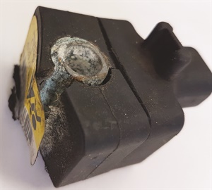
Corrosion and water intrusion is a common cause of a crash sensor failure, this sensor has swelled and is broken.
If corrosion is found, that sensor will need to be replaced along with possibly the pigtail. These FES sensors are prone to water intrusion and don’t need to be calibrated after installation. Simply use the scanner to erase the codes.
If no corrosion is evident, swapping the sensors side-to-side is an easy and quick way to diagnose a failed sensor, especially if the code is B0084-39 (internal sensor failure). The code should move to the other side and maintain the same suffix (remember to mark the sensors L/R so you know which is which). If the code doesn’t move, you are going to have to inspect the wiring and the SRS module and follow the appropriate diagnostics using the sub code as well in the service information.
Another common GM pickup SRS failure involves the side impact sensor located inside the left front door. These side impact crash sensors work by sensing the air pressure change during a collision as the door is crushed. If the code retrieved is a B0085-00 left front side impact sensor high circuit, look first at the wiring harness in the driver’s door jamb at the A-pillar. If the truck is used by a contractor or delivery service and the driver’s door is constantly being used, the wires that go to the crash sensor in the door have likely broken.
2001 to 2006 Honda Civics have a common failure in the seat belt buckle switch. There is a small three-wire switch that is located inside the female part of the seat belt that tends to fail. Because the SRS system needs to know if the occupants of the vehicle are wearing a seat belt, a switch failure will trigger the SRS light and typically set an SRS DTC 9-3: faulty driver’s seat belt buckle switch.
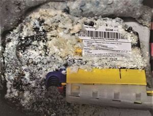
Another example of corrosion, this SRS module was under the driver’s seat of a Chevy Blazer that had a windshield leak.
Inspection for this code involves a voltmeter to check for voltages at the seat belt harness connector while it is still connected. Verifying that the buckle switch has a good ground is the first step. Back probing on the seat belt side of the connector is next. Key-on voltages should be:
- Black wire should always be a good ground.
- Voltage with seat belt buckled: red/blue wire = 5-12V, blue/red wire = 0V.
- Voltage with seat belt unbuckled: red/blue wire = 0V, and the blue/red wire = 4.5 to 5V.
These Honda Civics require a scan tool to retrieve the SRS codes and a scanner is recommended to erase the codes but isn’t required. You can use the yellow plastic memory erase signal (MES) connector, located in the fuse box and the special Honda SCS 07PAZ-0010100 tool (I have used a jumper I made from a used harness connecter after I removed the locking tang) and follow this procedure to erase the codes. I’ve had to do this procedure more than once to get the codes to erase. This procedure can save time as compared to using a scanner if you already know the SRS system has been repaired, say at a body shop.If these voltages aren’t found, unplug the connector and check for voltages on the harness side. The SRS module will need to see both circuits open or grounded at the same time to set the 9-3 code. The ground G551 for this switch is located underneath the front passenger seat, and can become corroded from water intrusion due to flooding or salt-laden winter boots.
- Key off.
- Connect the SCS tool to the NES connector.
- Key on.
- SRS indicator light on for about six seconds, then goes off. Remove the SCS tool within four seconds of SRS light going off.
- SRS light on again, reconnect the SCS tool within four seconds.
- SRS light off again, unplug the SCS tool within four seconds.
- If the SRS light should blinks twice indicating the code/codes are cleared.
- Key off wait 10 seconds, key on, SRS light should come on for about six seconds and go out.
It’s also important to note that Honda does not want you to repair the SRS wiring harnesses. According to their service information, if there is corrosion, the entire harness is supposed to be replaced.
Common SRS output issues
Many output issues can also be diagnosed with a non-factory scanner to retrieve and clear codes and provide system data that will aid in diagnosing the fault. A good volt ohm meter and a couple of other inexpensive and easily obtained parts will also help in many output issue diagnostics.
The SRS control module is constantly monitoring all of its circuits and components for the proper operation, resistance and shorts to power or ground to ensure that the equipment will function as designed when needed.
Because most SRS airbag inflator circuits are typically two-wire circuits, resistance issues are common. A resistance that is too high or too low will set codes. It’s important to remember that a seat belt pretensioner also features a small explosive charge monitored and controlled by a two-wire circuit.
The SRS control module is constantly monitoring all of its circuits and components for the proper operation, resistance and shorts to power or ground to ensure that the equipment will function as designed when needed.
The normal resistance across these inflator circuits is about 1 to 3 ohms and this data is usually displayed in the SRS data using a scan tool. Some newer Mazda models have a wider range of 0.8 – 9.85Ω. Diagnosing these circuits and resistance codes following the factory diagnostics usually requires specific SRS load tools to substitute the removed inflator/deployment circuits.
But the same testing can be achieved with a scan tool, up-to-date service information and a few 1/4 watt 1, 2, and 3Ω resistors. A 3Ω resistor will work just fine on the new Mazda, too.
The following common issues can all be diagnosed without any special equipment by just using a 2 or 3Ω test resistor in the component connector of concern. This test resistor will verify the integrity of the wiring and module operation. After you have gained access to the component connector that has the resistance issue and have confirmed that corrosion or a loose connection isn’t the issue, you can substitute the test resistor of the appropriate resistance into the circuit to simulate the inflator. Then clear the code and see if the code returns. If the code doesn’t return, the issue is likely in the inflator. If it does return the issue is in the wiring or module and more testing is going to be required.
2005-2009 Ford Escapes will set a code B2292 high resistance in the passenger side seat belt pretensioner circuit. The Ford spec is 3.2-1.4Ω, so installing a 2Ω test resistor will be used. (These Escapes had a fretting issue in the pretensioner connector and the simple act of disconnecting and reconnecting the connector would often rectify the issue.)
2011 Honda Civics set a code 27-10 (Open in the Driver’s Seat Belt Buckle Tensioner). The factory manual wants you to use the SRS Inflator Simulator 07SAZ-TB4011A and the 2Ω connector to simulate the seat belt pretensioner. Installing a 2Ω test resistor will do the same thing. Clear the codes. If the code is gone, the seat belt pretensioner is the issue. If the code doesn’t clear, further testing will be needed.
Using these test resistors also provides an easy test to verify a bad clock spring assembly.

After a collision that deploys the airbags like this one, there are a number of parts and pieces that are single use and will need to be set up to function properly again.
Using the shorting bars (if equipped) in the SRS connectors is another quick way of verifying an inflator circuit. Many SRS connectors have a spring-loaded shorting bar that shorts across the terminals in the SRS connector when the connector is disconnected or the connector position assurance (CPA) retainer lock is removed. If the SRS code relates to high resistance, you disconnect the connector and the SRS diagnostic code should change to a low resistance code due to the shorting bars. This verifies that circuit is good and that the cause of the high resistance is likely the inflator or the connection.
Common SRS controller issues
This category of repairs can be separated into two parts: SRS module replacement and occupant classification system (OCS) recalibration. Each part has its own issues, complexity and tool use requirements.
Most SRS modules are good for one collision event and will need to be replaced after a collision. The service information is very specific on what parts and pieces need to be replaced after a crash and most SRS modules will need to be set up, programmed or re-calibrated after repairs. This is different from most seat belt pretensioners, airbags and crash sensors that typically don’t require to be set up and are plug and play.
After SRS module replacement, many vehicles may require a factory scanner and possibly factory-based internet service to complete the replacement. It is very important to thoroughly read the proper service information and know what your scan tool capabilities are before you commit to SRS module replacements and setup. This same situation can arise if a TSB indicates that a reflash or programming update is required.
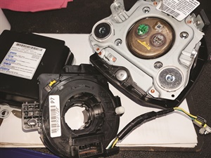
These components all needed to be replaced after a collision. The clock spring was damaged when the airbag deployed, and the SRS module is only good for one accident event or deployment.
Most SRS module setups need very specific routines and procedure to be completed for them to be initialized. Not following all the correct steps often leads to other unrelated SRS codes.
All late model GM vehicles now require that you subscribe to their SPS information service and use the web site for the proper setup of their SRS systems when a new SRS module is installed. It also sets up the OCS and other system components as needed. Ford’s SRS modules can’t be handled without the use of a scan tool that can install the SRS as-built data or flash the module with the required software. Honda, Toyota and almost all European cars are similar, and many Chrysler SRS modules come totally blank.
Occupant classification system recalibration or zeroing is a common concern after a collision or SRS module replacement. These procedures may or may not require a factory scan tool to perform. Knowing your scan tool limitations is imperative.
Successful SRS repairs involve basics and the proper information
The appropriate up-to-date service information is vital for a successful SRS repair and diagnostic and that information should be followed carefully to ensure a complete repair and to prevent other issues.
Attention to seemingly trivial details is important, from proper wiring repairs to the correct fastener torque specifications of SRS modules, airbags and seat belts. Other basics such as working with a fully charged battery before and during a flashing or programming event or the OCS setup will ensure a proper repair.
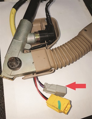
Many SRS connectors feature a built-in shorting bar. The arrow indicates the shorting bar in the connector.
Thoroughly reading and understanding the SRS failure code is important. Honda issued a service bulletin that points out that a problem in the front passenger’s side airbag inflator or the drivers side airbag inflator isn’t the airbag assembly in the dash or the steering wheel, as many techs assumed. Carefully reading the SRS code they can easily miss the word SIDE in the code or component description and in the case of a Honda, that means the side airbag assemblies in the seats.
Ensuring that all the connector position assurance (CPA) retainer locks are installed is critical or the shorting bars could still be engaged, possibly setting a code that wasn’t there before. Little CPA’s are commonly used on the driver’s airbag and they can easily be damaged, dropped or misplaced during a non-SRS service, such as an ignition switch, turn signal switch or steering column service. The result is an SRS light on and a low resistance code that wasn’t there before the repair, even though the connector is properly attached.
Another common SRS system issue involves no module communication or code display, but an illuminated SRS light. This issue can be the result of the wrong parts being installed, unprogrammed modules, unseen wiring damage or by components that aren’t set up correctly. But this can also be caused by a reset/refurbished SRS module. Remembering that they are single-use is important, as is asking about the vehicle history or previous repairs, which may save time in an SRS diagnostic.
There are some safe shortcuts that can be used to successfully diagnose some SRS faults. Yes, a scanner is likely going to be required for diagnostics and repairs, but it may not have to be a factory tool. And with the proper techniques, the correct equipment, full vehicle history, up-to-date service information and a working knowledge of the system, an SRS issue should be no more difficult to diagnose than many of today’s modern engine controls.
Want to see how ALLDATA can improve shop efficiency? Check out our suite of products, each designed to contribute to both shop efficiency and productivity.
If you would like to read more articles like this one please subscribe to ALLDATA News.
